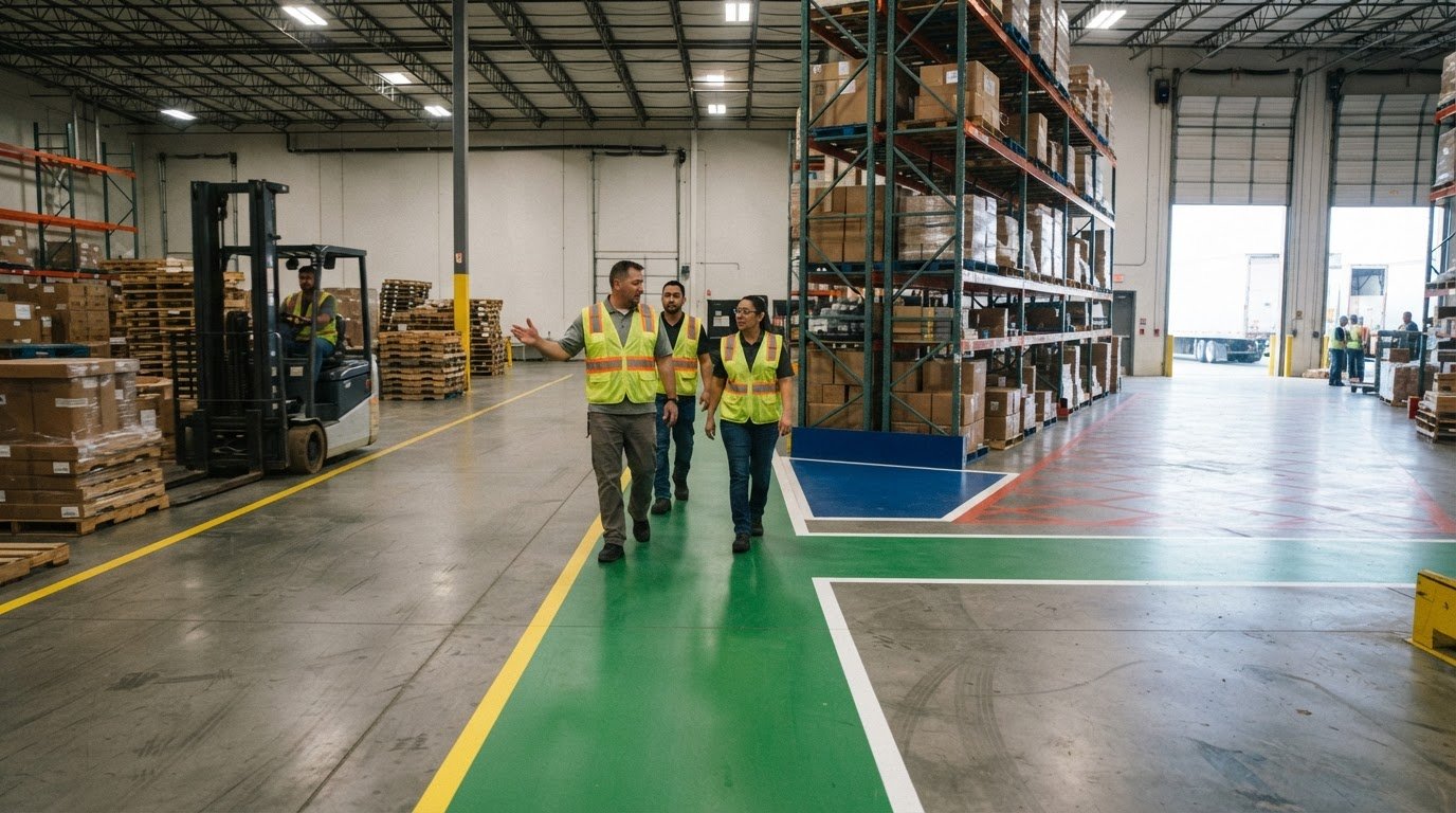
The clearest-looking floor line isn’t automatically the right guide for an AGV. Optical systems follow high-contrast lines, color sensors track a consistent specified color, and magnetic systems detect magnetic tape; inductive-wire systems follow wire installed in the floor. That’s why floor markings for automated guided vehicles (AGV) must match the vehicle’s guidance method, route layout, and operating conditions. Project pricing depends on the case and is provided after a quote request, with material, floor preparation, route length, and layout shaping the work.
Cost matters, but so do the route’s requirements: turns, intersections, stopping points, and pedestrian areas all affect how markings work in a warehouse. This article explains how common AGV guidance methods use floor references, what to consider when planning routes and safety markings, and which factors shape the project scope. You’ll get a clearer basis for matching the marking approach and work to your facility’s needs.
Key Takeaways
- Match the route-marking method to the AGV’s guidance system; paint alone won’t guide a vehicle that relies on magnetic tape or embedded wire.
- Plan pedestrian areas and vehicle paths together so floor markings support clear, predictable movement through shared workspaces.
- Design turns, intersections, and pickup points around the AGV’s tracking needs to reduce route interruptions and missed stops.
- Floor-marking costs depend on factors such as surface preparation, materials, route complexity, and the amount of marking required.
- When a route changes, removing outdated markings can help prepare the floor for a clearer revised layout.
Optical, color-sensor, magnetic-tape, and inductive-wire guidance
AGVs follow different physical or visual references, including optical lines, colored paths, magnetic tape, and floor-installed wire. The right marking depends on what the vehicle’s sensors detect and how its route is designed.
Magnetic-Tape and Inductive-Wire Guidance
Magnetic-tape guidance uses sensors beneath an AGV to detect a magnetic element in floor tape; inductive-wire guidance follows wire installed in the floor. This distinction matters: ordinary paint cannot guide a magnetic-tape vehicle, while wire guidance needs an installed route rather than a surface line. Magnetic track can be used on different floor surfaces, though suitability depends on the installation.
Track Guidance and Sensor Detection
Track guidance means an AGV uses a defined floor reference and onboard sensors to follow a lane. In absolute guidance, floor markers such as magnetic points or barcodes can provide position references at one-meter intervals in the described GRID method. Relative track guidance lets a vehicle leave its usual lane to approach a cart, using spatial markers detected by cameras. The guidance method affects how the route handles exceptions.
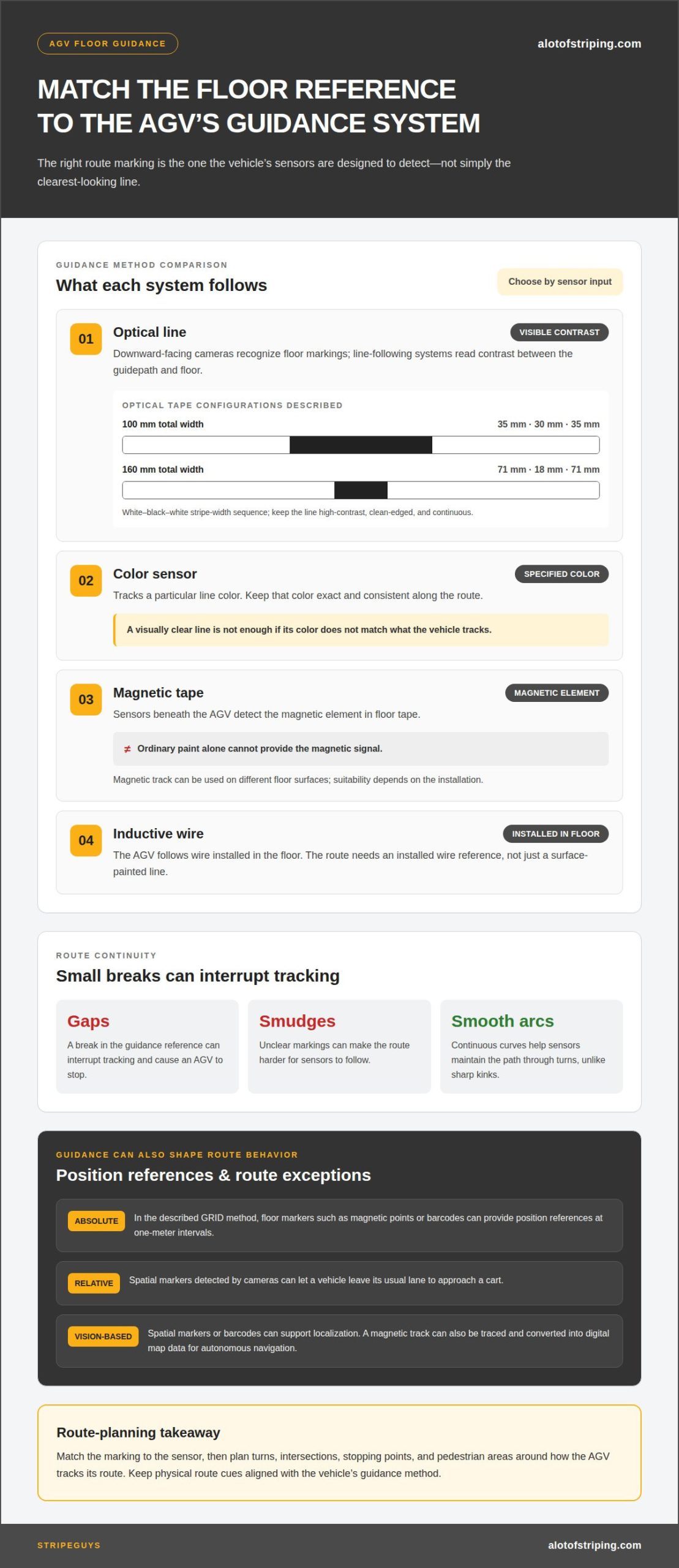
Optical AGVs use downward-facing cameras to recognize floor markings through signal colors or barcode tapes. A line-following system reads contrast between its guidepath and the floor, so the line needs high contrast, clean edges, and continuity. Standard optical guidance tape is available in a 100 mm width, with white, black, and white stripes measuring 35 mm, 30 mm, and 35 mm. Another configuration is 160 mm wide, with stripes measuring 71 mm, 18 mm, and 71 mm.
Color-sensor vehicles track a specific line color, so keep that color exact and consistent along the route. Magnetic-tape vehicles detect the tape’s magnetic element instead; paint alone won’t provide that signal. For either approach, gaps, smudges, or breaks can interrupt tracking and cause an AGV to stop. Smooth, continuous arcs help sensors maintain the path through turns, unlike sharp kinks.
Vision-based guidance can use spatial markers or barcodes for localization instead of relying only on a continuous line. A virtual guideline can be created by tracing a magnetic track and converting its route into digital map data. An autonomous vehicle can then navigate using mapped information, while physical references remain useful for sensor detection and lane guidance.
Choose markings to suit the AGV’s guidance technology, not appearance alone. Optical lines need visible contrast, color-sensor paths need a consistent color, magnetic systems need magnetic tape, and inductive systems need floor-installed wire. This distinction helps facilities select a guidance method suited to their AGVs’ scheduled travel and route changes.
AGV safety and workplace efficiency
AGV safety depends on clear routes, effective obstacle detection, and controls suited to the work area. Worn, obstructed, or ambiguous markings can confuse route guidance, interrupt tracking, and make traffic less predictable for nearby workers.
Safety Standards and Requirements
ANSI/ITSDF B56.5-2019 is listed as a U.S. safety standard for automated guided vehicles, making it a key reference for industrial transport planning. The named standards include emergency-stop devices on every AGV. ANSI/RIA 15.08 Part 1 specifies safety requirements for industrial mobile robots, while Part 2 addresses integrating, configuring, and customizing systems at a site. Together, these standards frame both vehicle and facility considerations.
Risks from Marking Conditions
Marking-related risks arise when route cues are worn, blocked, or unclear to sensors and people. An AGV may lose tracking or stop if its guidance reference is interrupted, while a worker may misread an unclear boundary or direction. These issues matter especially where people and vehicles share aisles, crossings, or pickup areas.
Obstacle detection supports safer movement, but it doesn’t remove every risk. An AGV may not stop sufficiently when an object enters its path unexpectedly. Facilities should therefore plan for both sensor-based detection and clear separation between vehicle lanes and pedestrian routes. Marked walkways and floor signs help alert people to AGVs. At least 80 percent of U.S. forklift accidents involve a pedestrian, making clear traffic organization an important workplace consideration.
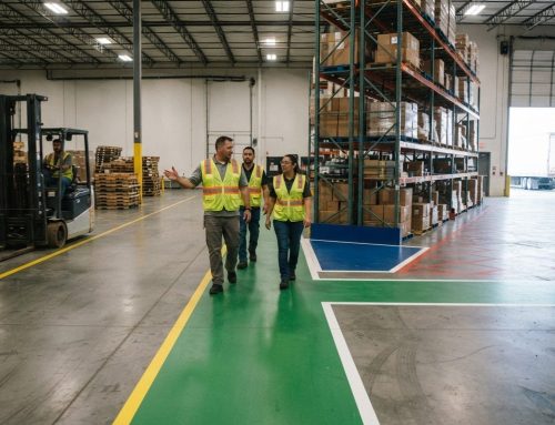
Markings can communicate where workers should walk and where automated transport should travel. For example, a visible pedestrian walkway beside an AGV lane gives people a defined route instead of leaving them to cross vehicle paths unpredictably. A facility can use pedestrian walkways and safety aisles to make those boundaries clear.
Safety planning also needs to account for changing work conditions. Floor tags or transponders can tell magnetic-, wire-, and optically guided AGVs which protective-field set to use. This connects route information with how the vehicle responds in different operating areas. If layouts or tasks change, keep route cues and the vehicle’s safety configuration aligned.
Clear, consistent marking can support smoother transport by reducing uncertainty at shared aisles and crossings. AGVs have the capacity to increase efficiency by 50 to 70 percent, but effective implementation also involves safety planning, compatibility checks, employee training, and workflow optimization. The markings are one part of that system, alongside vehicle sensors, protective fields, and the way people move through the facility.
Route layout, turns, intersections, and stopping points
Optical tape options include widths of 100 mm and 160 mm, with white-and-black stripe patterns. Marker spacing depends on the guidance method: one simulated route worked perfectly with markers less than 700 cm apart.
Track Layouts and Route Elements
An AGV track layout connects straight lanes, curves, forks, switches, and crossings into a route. Each element guides the vehicle through a different part of its operation. For example, a fork can direct an AGV toward separate production areas, while a crossing defines where routes intersect.
Plan the visual path around actual facility movement. A route crossing a forklift aisle needs a clearly defined path through that conflict point. Keep markings continuous between route elements so the AGV can follow its track without encountering an unexplained gap.
Turns, Intersections, and Stopping Points
Turns, intersections, and stopping points guide direction, manage shared paths, and position the AGV for work. Their placement matters: a corner beyond the vehicle’s tracking ability can make it leave the line. Smooth, continuous arcs give sensors a clearer path than sharp kinks.
At merges and crossings, define how each AGV track continues through the conflict area, including where it crosses forklift aisles. Mark pickup and drop-off dwell points so the vehicle stops in the correct position, rather than short of a cart or station.
Marker Spacing and Route Following
Marker spacing is the distance between floor references used to help an AGV follow a route or determine its position. It matters because a vehicle needs enough reference information to navigate its path accurately. In one simulation, the AGV followed its route perfectly when markers were less than 700 cm apart; tests also included 300 cm and 700 cm spacing.
That simulation result isn’t a universal spacing specification. The described GRID localization method places magnetic points or barcodes at one-meter intervals. These examples show why spacing must suit the guidance technology and route design, rather than being copied across every operation.
Marking Widths and Colors
Marking widths and colors are the visual dimensions and contrasts an optical guidance system reads. They matter because sensor detection depends on a consistent pattern. One optical tape format is 100 mm wide, with white, black, and white stripes measuring 35 mm, 30 mm, and 35 mm.
A second format is 160 mm wide, with white stripes of 71 mm on either side of an 18 mm black stripe. These are available configurations, not universal requirements for every AGV. Choose a pattern compatible with the vehicle’s optical guidance system and maintain it consistently along the route.
Warehouse floor-marking price range
Inspect AGV markings during routine floor checks and after floor repairs, coating work, or layout changes. Clean optical guidepaths when dust or residue reduces contrast, and repair worn sections before tracking is interrupted. Replace or remark paths when wear, resurfacing, or route changes prevent a continuous, readable guide. Wheels, forklift crossings, and pedestrian traffic all affect how quickly markings wear.
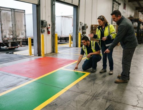
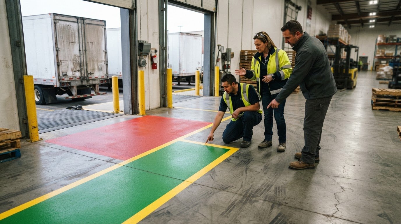
Use distinct, consistent visual cues to separate pedestrian lanes, AGV crossings, and hazard zones. Mark pedestrian walkways and use floor signs to alert workers to vehicle routes; define crossings where people and AGVs share access. Make each transition clear instead of relying on color alone to explain an unfamiliar or ambiguous boundary.
Warehouse floor-marking price depends on the case and is provided after a quote request; material, surface preparation, route length, and layout complexity affect the work. A short, straight route on a sound surface involves different preparation from a long route with several intersections and worn markings to remove. The quantity of line work and the condition of the concrete shape the project scope.
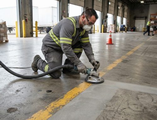
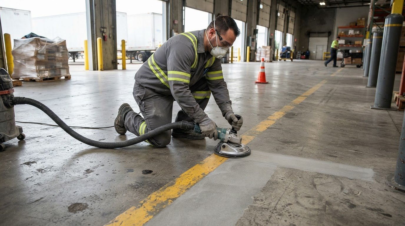
Preparation matters because markings need a suitable surface to bond and remain continuous. Clean, dry concrete may still require abrasion before application. Existing lines also affect the work: obsolete routes may need removal before new paths are installed. For example, if a revised AGV system moves a pickup point, the former stop marking may need to be removed and new markings applied along the changed route.
Route components add work when each needs separate layout and application. A warehouse plan may include straight travel lanes, curves, branches, crossings, pedestrian walkways, and pickup or drop-off points. Each element helps robots navigate, while the combined layout affects labor and preparation. Forklift traffic across an AGV path can also increase wear and influence material choices.
For a useful project scope, identify the AGV guidance method, route length, floor condition, existing markings, and required pedestrian boundaries. These details connect the agv system’s ability to follow its route with the marking work needed on site. To discuss a warehouse layout and marking scope, request a floor-marking quote.
StripeGuys Warhouse Line Striping: Floor marking removal
StripeGuys provides warehouse line removal to clear outdated markings that could conflict with a revised AGV route. Removing obsolete lines helps make the new layout easier for vehicle sensors and warehouse staff to read. When a route changes, line removal can prepare the floor for updated warehouse floor striping, including clear lanes, crossings, and pickup points.
For facilities that need a different marking approach, StripeGuys also provides epoxy line painting. The right scope depends on the existing markings, floor condition, and intended layout. Contact StripeGuys Warhouse Line Striping to discuss floor marking removal for your warehouse.
Set the Next Marking Project Up for Success
Use the next route change as an opportunity to align floor decisions with the warehouse’s operating plan. Before work begins, define which AGV paths will remain, which markings need removal, and how the revised layout should support future material flow. This gives the project a clear scope and helps teams coordinate floor work with operational changes.
Planning floor markings for automated guided vehicles (AGV) also means considering the facility beyond the vehicle route. StripeGuys provides warehouse floor striping and epoxy line striping for industrial spaces, as well as parking lot line striping for exterior traffic areas. The appropriate service depends on the surface and marking needs of each area.
Share your project goals and the areas that need attention to start a focused conversation about the work. Contact StripeGuys Warhouse Line Striping to discuss your facility’s marking plans. A clear scope is a practical first step toward a more organized operation.
Frequently Asked Questions
4.1 What are the different AGV operating zones?
AGV operating zones are functional areas where vehicles travel, interact with people, or perform tasks. A warehouse plan might define travel aisles, shared crossings, pickup and drop-off points, and charging locations as separate zones. Each has a distinct purpose, so its route cues should support that activity. For example, a pickup zone needs a clearly identified stopping position, while a shared crossing needs visible pedestrian and vehicle paths.
What is AGV guidepath floor marking?
AGV guidepath floor marking is a physical reference on or within the floor that helps a guided vehicle follow a planned route. In practice, floor markings for automated guided vehicles (AGV) may be a visible line, magnetic tape, barcode, or installed wire. A camera-guided vehicle can read a contrasting line, while a magnetic sensor detects magnetic tape. The guidance method determines which floor reference the vehicle can use.
What is the difference between a virtual and a physical guideline?
A physical guideline is a tangible floor reference, such as a magnetic strip, barcode, or optical line. A virtual guideline is route information represented in a digital map rather than a continuous surface marking. For example, a magnetic track can be traced and converted into map data. A facility may use mapped routes for navigation while retaining physical markers where vehicles need specific position references.
What types of floor markings guide automated guided vehicles (AGVs)?
AGVs can use optical lines, colored tape, magnetic tape, barcodes, floor markers, or wire installed in the floor. The suitable type depends on the vehicle’s sensors and navigation setup. A camera may recognize a barcode or visual line, while a magnetic sensor detects magnetic tape. Inductive-wire vehicles follow wire beneath the floor, so a painted line alone doesn’t provide their guidance signal.
Do AGVs use painted lines, magnetic tape, barcodes, or floor markers for navigation?
Yes. AGV systems use different references, and some use more than one. The right floor markings for automated guided vehicles (AGV) depend on the navigation equipment: optical systems read contrast, color sensors track a specified line color, and magnetic systems detect magnetic tape. Cameras can also read barcodes or spatial markers. These options aren’t interchangeable, so the vehicle’s system determines which reference it can interpret.
What U.S. OSHA or ANSI standards apply to AGV floor markings and traffic lanes?
ANSI/ITSDF B56.5-2019 is identified as a U.S. AGV safety standard, and ANSI/RIA 15.08 covers industrial mobile robot safety and system integration. OSHA’s 29 CFR 1910.22(b) is the subject of StripeGuys’ warehouse floor-marking compliance resource. These references address safety and workplace conditions; they don’t establish one universal AGV floor-marking color or layout. Markings should suit the vehicle guidance and facility traffic plan.